DIY Ventilator Using Arduino
Make A DIY Low Cost Ventilator With Temperature, BPM & Oximeter
Introduction
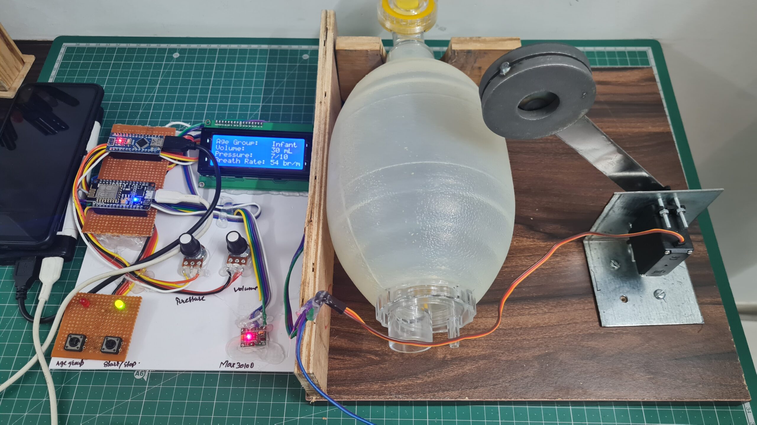
In This Blog, I will Explain DIY Ventilators and How You Make Them. I will explain all the things how you connected to all the sensors and LCD And How You Used them In Emergencies.
The ventilator will be designed and developed using Arduino And esp8266. It provides many functions and is also a reliable yet affordable DIY Ventilator to help in times of Pandemic.
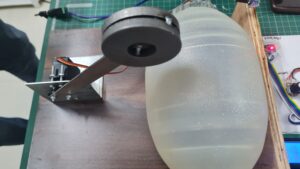
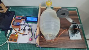
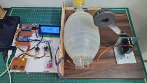
Here We Use a silicon Ventilator bag coupled with a Servo motor With a Liner Arm Mechanism To Push the Ventilator Bag. You just press the push button ventilator will start and a variable pot to adjust the Pressure And Volume.
Apart from this the ventilator must also monitor the patient’s blood oxygen level and exhaled lung pressure to avoid over and under-air pressure simultaneously.
The Entire system is driven by an Arduino controller to achieve desired results and also assist patients in Emergencies.
Bill Of Materials
S.N. | Component | Quantity | Buy Link |
1 | Arduino Uno | 1 | |
2 | 20x4 Lcd Display | 1 | |
3 | 10k Port | 2 | |
4 | Push Button | 2 | |
5 | Servo Motor (MG995) | 1 | |
6 | NodeMcu(Esp8266) | 1 | |
7 | Max30100 Sensor | 1 | |
8 | DHT11 Sensor | 1 | |
9 | 12v 2 Amp Power Supply | 1 | |
10 | AMBU Bag | 1 | |
11 | LED | 1 | |
12 | Zero PCB | 2 |
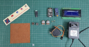
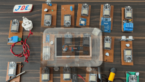
Let’s see the All Components That I used in this project’s
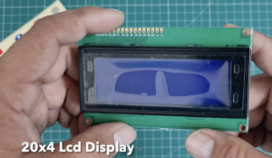
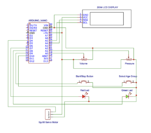
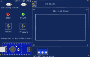
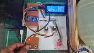
Here I Used The 20×4 LCD And They Will be Connected To The Pin Number
- GND GND
- VCC 5V
- SDA A4
- SCL A5
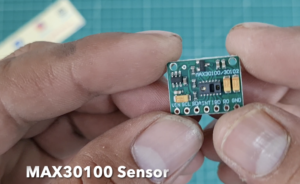
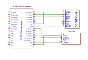
MAX30100 Is Connected To The Esp8266 Board and Is Measuring The Heart Bit And Sp02. And They Will Connected To The PIN Number
- VCC. 5v
- GND GND
- SDA D2
- SCL D1
- INO D0
In this Project, I Used The MG-995 Servo Motor because it required More torque And was connected To The Arduino Pin Number D4.
Here I used To 10k Pot To The Volume And Pressure Of the Servo Motor just Rotate The pot clockwise or anti-clockwise And The volume and pressure will change They will be connected to the Arduino Pin Numbers A0 And A1.
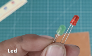
The LED indicates whether your system will Start or Stop. The Red LED will Glow When the system stops and the green LED will glow when your system starts. and they connected to the PINs D7 And D8.
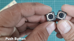
With the help of the push button, you select the Age Group. they connected to the PIN D7 And D8 in Arduino nano Board. with the help of the push button, you start and stop the system and you also select the age group.
In the Zero PCB, I soldered the all components.
This One DC Female jack and I provide the 9 to 12v external Power Supply.
Block Diagram
- Here I Explain the Block Diagram of this Project I hope You understand What I Used In This Project InPut Side Or Output Side
- Psuh Button, PoT(Variable Resister), MAX30100 And DHT11 Sensor Is Input Device
- Led, Lcd(20×4 LCD Display) And Servo motor is Output Device
Circuit Diagram
I Make The Circuit Diagram Using The EasyEda Software. AI will just Show The Pin Where I connected To The Input/Output Sensor.
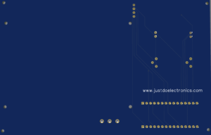
PCB Design:-
Source Code/Program
Before You Uploading The Code First add it to Library Servo.h And constants. h
|
1 2 3 4 5 6 7 8 9 10 11 12 13 14 15 16 17 18 19 20 21 22 23 24 25 26 27 28 29 30 31 32 33 34 35 36 37 38 39 40 41 42 43 44 45 46 47 48 49 50 51 52 53 54 55 56 57 58 59 60 61 62 63 64 65 66 67 68 69 70 71 72 73 74 75 76 77 78 79 80 81 82 83 84 85 86 87 88 89 90 91 92 93 94 95 96 97 98 99 100 101 102 103 104 105 106 107 108 109 110 111 112 113 114 115 116 117 118 119 120 121 122 123 124 125 126 127 128 129 130 131 132 133 134 135 136 137 138 139 140 141 142 143 144 145 146 147 148 149 150 151 152 153 154 155 156 157 158 159 160 161 162 163 164 165 166 167 168 169 170 171 172 173 174 175 176 177 178 179 180 181 182 183 184 185 186 187 188 189 190 191 192 193 194 195 196 197 198 199 200 201 202 203 204 205 206 207 208 209 210 211 212 213 214 215 216 217 218 219 220 221 222 223 224 225 226 227 228 229 230 231 232 233 234 235 236 237 238 239 240 241 242 243 244 245 246 247 248 249 250 251 252 253 254 255 256 257 258 259 260 261 262 263 264 265 266 267 268 269 270 271 272 273 274 275 276 277 278 279 280 281 282 283 284 285 286 287 288 289 290 291 292 293 294 295 296 297 298 299 300 301 302 303 304 305 306 307 308 309 310 311 312 313 314 315 |
//Prateek //https://justdoelectronics.com #include <Servo.h> #include <LiquidCrystal_I2C.h> #include "constants.h" const int8_t pot_map_radius[3] = { 5, 5, 5 }; const uint16_t nom_vals[3][3] = { { 500, 300, 25 }, { 5, 5, 5 }, { 12, 25, 50 } }; const uint8_t val_inc[3][3] = { { 10, 5, 1 }, { 1, 1, 1 }, { 1, 1, 2 } }; const uint16_t base_delays[3] = { 950, 550, 200 }; const char clear_value[] = " "; const char *setting_titles[3] = { "Volume: ", "Pressure: ", "Breath Rate: " }; const char *age_titles[3] = { "Adult", "Child", "Infant" }; const char *unit[3] = { " mL", "/10", " br/m" }; bool ventilating = false; bool time_to_squeeze = true; bool time_to_release = true; long squeeze_time = -100; long release_time = -100; bool compression_state = 0; bool halt = false; bool warn_user = false; bool can_read_age_button = true; long age_button_time = -100; bool can_read_start_button = true; long start_button_time = -100; int8_t pot_vals[3] = { 0, 0, 0 }; uint8_t age_state = 0; long red_led_flash = 0; bool red_led_flash_on = false; double sensitivity[] = { 0.185, 0.100, 0.066 }; double voltage; double current_sum = 0; Servo servo; LiquidCrystal_I2C lcd(0x27, 20, 4); int map_pot_val(uint16_t unmapped_pot_val, int8_t pot_index) { return map(unmapped_pot_val, 0, 1024, pot_map_radius[pot_index], -pot_map_radius[pot_index]); } int16_t map_servo_pos(int16_t pos) { return map(pos, 0, MAX_SERVO_POS, 180, 0); } void lcd_update(uint8_t pot_index) { lcd.setCursor(LCD_H_SPACING - 1, pot_index + POT_LCD_OFFSET); lcd.print(clear_value); lcd.setCursor(LCD_H_SPACING, pot_index + POT_LCD_OFFSET); int16_t val = nom_vals[pot_index][age_state] + val_inc[pot_index][age_state] * pot_vals[pot_index]; lcd.print(val); lcd.print(unit[pot_index]); } void lcd_update_age() { lcd.setCursor(LCD_H_SPACING - 1, 0); lcd.print(clear_value); lcd.setCursor(LCD_H_SPACING, 0); lcd.print(age_titles[age_state]); for (uint8_t i = 0; i < 3; ++i) { lcd_update(i); } } void lcd_startup() { lcd.clear(); lcd.setCursor(8, 0); lcd.print("YOUR"); lcd.setCursor(0, 2); lcd.print("Automatic Inhalation"); lcd.setCursor(4, 3); lcd.print("VENTILATOR"); } void lcd_init_titles() { lcd.clear(); lcd.setCursor(0, 0); lcd.print("Age Group:"); lcd.setCursor(0, 1); lcd.print("Volume:"); lcd.setCursor(0, 2); lcd.print("Pressure:"); lcd.setCursor(0, 3); lcd.print("Breath Rate:"); } void lcd_init() { lcd_init_titles(); lcd_update_age(); } void check_pot_vals() { for (uint8_t i = 0; i < 3; ++i) { if (map_pot_val(analogRead(i + POT_PIN_OFFSET), i) != pot_vals[i]) { pot_vals[i] = map_pot_val(analogRead(i + POT_PIN_OFFSET), i); lcd_update(i); } } } void check_age_setting() { if (!digitalRead(P_SETTING_BUTTON) && can_read_age_button) { age_button_time = millis(); can_read_age_button = false; age_state = (age_state + 1) % 3; lcd_update_age(); } } void check_start_stop() { if (!digitalRead(P_START_BUTTON) && can_read_start_button) { if (warn_user) { red_led(true); warn_user = false; lcd_init(); } else { start_button_time = millis(); can_read_start_button = false; ventilating = !ventilating; red_led(!ventilating); green_led(ventilating); } } } bool check_halt() { if (ventilating && warn_user) { return true; } bool was_ventilating = ventilating; check_start_stop(); if (was_ventilating && !ventilating) { return true; } return false; } uint8_t get_servo_delay() { uint16_t des_delay = nom_vals[PRES][age_state]; des_delay += val_inc[PRES][age_state] * pot_vals[PRES]; des_delay = map(des_delay, nom_vals[PRES][age_state] - pot_map_radius[PRES] * val_inc[PRES][age_state], nom_vals[PRES][age_state] + pot_map_radius[PRES] * val_inc[PRES][age_state], MIN_SPEED, MAX_SPEED); return des_delay; } void drive_servo(uint16_t desired_pos) { uint16_t servo_pos = servo.read(); if (servo_pos < desired_pos) { for (int16_t pos = servo_pos; pos < desired_pos; pos += 1) { halt = check_halt(); if (halt) { break; } servo.write(pos); delay(6); } } else { for (int16_t pos = servo_pos; pos > desired_pos; pos -= 1) { halt = check_halt(); if (halt) { break; } servo.write(pos); update_current(); uint8_t del = get_servo_delay(); delay(del); } } } uint16_t get_ms_per_breath() { uint8_t breath_per_min = nom_vals[RATE][age_state] + val_inc[RATE][age_state] * pot_vals[RATE]; return round(1000 / (breath_per_min / 60.0)); } uint16_t vol_to_ang(uint16_t vol) { return 4.89427e-7 * pow(vol, 3) - 8.40105e-4 * pow(vol, 2) + 0.64294 * vol + 28.072327; } void red_led(bool on) { analogWrite(P_RED_LED, on ? 5 : 0); } void green_led(bool on) { digitalWrite(P_GREEN_LED, on ? HIGH : LOW); } void flash_red() { if ((millis() - red_led_flash) > 200) { red_led(!red_led_flash_on); red_led_flash_on = !red_led_flash_on; red_led_flash = millis(); } } double predict_current() { uint16_t v = nom_vals[0][age_state] + val_inc[0][age_state] * pot_vals[0]; uint8_t p = nom_vals[1][age_state] + val_inc[1][age_state] * pot_vals[1]; return -1.041041e3 + 2.35386 * v + 2.316309e-3 * pow(v, 2) - 3.887507e1 * p + 7.7198644 * pow(p, 2) - 4.2099326e-2 * v * p; } void update_current() { uint16_t potentiometer_raw = analogRead(P_CURRENT); double voltage_raw = (5.0 / 1023.0) * analogRead(VIN); voltage = voltage_raw - QOV + 0.012; double current = voltage / sensitivity[MODEL] * -1; current_sum += current; } void setup() { Serial.begin(9600); pinMode(P_RED_LED, OUTPUT); pinMode(P_GREEN_LED, OUTPUT); pinMode(P_SETTING_BUTTON, INPUT_PULLUP); pinMode(P_START_BUTTON, INPUT_PULLUP); servo.attach(P_SERVO); servo.write(map_servo_pos(START_POS)); lcd.init(); lcd.backlight(); lcd_startup(); red_led(true); green_led(true); delay(3000); lcd_init(); green_led(false); } void loop() { if (!can_read_age_button && millis() - age_button_time >= 500) { can_read_age_button = true; } if (!can_read_start_button && millis() - start_button_time >= 500) { can_read_start_button = true; } if (!warn_user) { if (!ventilating) { check_age_setting(); } check_pot_vals(); } if (halt) { compression_state = 0; ventilating = false; drive_servo(map_servo_pos(START_POS)); release_time = millis(); } halt = check_halt(); if (warn_user) { flash_red(); } if (ventilating) { uint16_t ms_per_breath = get_ms_per_breath(); int16_t post_breath_delay = ms_per_breath - base_delays[age_state]; if (post_breath_delay < 0) { post_breath_delay = 1000; } if (time_to_squeeze && !compression_state) { compression_state = 1; uint16_t des_vol = nom_vals[VOL][age_state]; des_vol += val_inc[VOL][age_state] * pot_vals[VOL]; uint16_t dest = vol_to_ang(des_vol); if (age_state == 0) { dest = map(dest, 193, 208, 180, 250); } drive_servo(map_servo_pos(dest)); squeeze_time = millis(); } else if (time_to_release && compression_state) { if (current_sum >= predict_current() * 1.2 && age_state == 0) { halt = true; green_led(false); warn_user = true; } else { compression_state = 0; drive_servo(map_servo_pos(START_POS)); release_time = millis(); } current_sum = 0; } if (compression_state) { update_current(); } time_to_squeeze = millis() - release_time > post_breath_delay; time_to_release = millis() - squeeze_time > base_delays[age_state]; } } |
Demo Of Project
Video Tutorial & Guide
Conclusion
Building a low-cost ventilator with integrated temperature, BPM, and oximeter capabilities using Arduino provides an affordable alternative for emergencies where access to traditional medical equipment is limited. However, it is crucial to note that this DIY ventilator should only be considered a temporary solution and should not replace professionally manufactured and tested medical devices. It is essential to consult healthcare professionals and follow local regulations and guidelines before using such a DIY ventilator in a medical setting.














Where is constants.h file please?