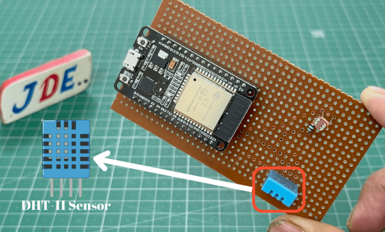
ESP32 DHT11 Temperature and Humidity Sensor
ESP32 with DHT11/DHT22 Temperature and Humidity Sensor using Arduino IDE
Introduction
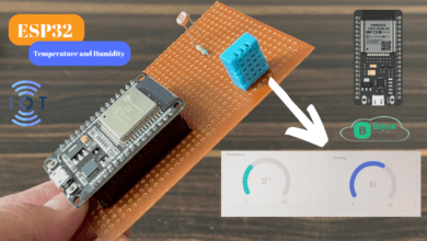
In this article we interface the DHT11 sensor with the ESP32 Board and display reading in Serial monitor,16×2 LCD Display And Oled Display.
DHT11 Sensor Measures the temperature and humidity and is a digital sensor that’s why we conected the digital pin to the esp32 board.
In DHT11 Sensor is only 3 Pin first is VCC, Digital Output And GND.
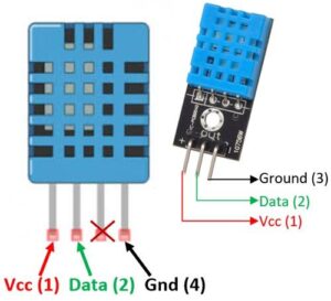
We conected the VCC pin in 5v, the Data pin is conected to Pin Number D14 and GND is conected to the GND of the ESP32 Board.
Guide For How You Install ESP32 Board In Arduino IDE software
Bill Of Materials
S.N | Component's | Quantity | Link To Buy |
1 | ESP32 Board | 1 | |
2 | DHT11 Sensor | 1 | |
3 | Zero PCB | 1 | |
4 | USB Cable | 1 |
Component’s
- In ESP32 Board Is Integrated with Wi-Fi And Dual-Core, Low Power Bluetooth, Low Power Consumption, and High performance.
- ESP32 Is a small-size Size Board And Has Soo many pins available To Connect to the input and output Devices.
- Compared to the Esp8266 Board Are so many Analog pins Available On the ESP32 Board and it Takes Low Power.
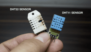
The DHT11 and DHT22 both sensors measure temperature & humidity in analog format and are converted into digital signals by an internal analogue-to-digital converter (ADC) within the sensor chip.
Specifications of the DHT11 sensor
- Temperature Range: 0°C to 50°C (32°F to 122°F).
- Temperature Accuracy: ±2°C.
- Humidity Range: 20% to 90%.
- Humidity Accuracy: ±5%.
- Resolution: 1°C for temperature measurements & 1% for humidity measurements.
- Response Time: 2 seconds for temperature readings & 2-5 seconds for humidity readings.
- Supply Voltage: 3.3V and 5V DC.
- Current Consumption: 1.5mA
- Communication: single-wire (Digital Sensor).
- Sampling Rate: 2 seconds.
Circuit Diagram
In this circuit diagram we interface the DHT11 Sensor first pin is conected to the VIN pin RED Wire, the Middle pin is conected to the D14 pin number(Blue Wire) And the third pin is conected to the Ground (Black Wire).
- When is connection is done you open the Arduino IDE software copy the code paste it into Arduino IDE select the proper board and upload it.
- when the code is successfully uploaded in the esp32 board then you just open the serial monitor and check the reading of the sensor.
Code
|
1 2 3 4 5 6 7 8 9 10 11 12 13 14 15 16 17 18 19 20 21 22 23 24 25 26 27 28 29 30 31 32 33 34 35 36 37 |
//Prateek //https://justdoelectronics.com //https://www.youtube.com/@JustDoElectronics/videos #include <DHT.h> #define DHT11_PIN 14 DHT dht11(DHT11_PIN, DHT11); void setup() { Serial.begin(9600); dht11.begin(); } void loop() { float humi = dht11.readHumidity(); float tempC = dht11.readTemperature(); float tempF = dht11.readTemperature(true); if (isnan(tempC) || isnan(tempF) || isnan(humi)) { Serial.println("Failed to read from DHT11 sensor!"); } else { Serial.print("Humidity: "); Serial.print(humi); Serial.print("%"); Serial.print(" | "); Serial.print("Temperature: "); Serial.print(tempC); Serial.print("°C ~ "); Serial.print(tempF); Serial.println("°F"); } delay(2000); } |
With 16×2 LCD Display (I2C)
|
1 2 3 4 5 6 7 8 9 10 11 12 13 14 15 16 17 18 19 20 21 22 23 24 25 26 27 28 29 30 31 32 33 34 35 36 37 38 |
//Prateek //https://justdoelectronics.com //https://www.youtube.com/@JustDoElectronics/videos #include <DHT.h> #include <LiquidCrystal_I2C.h> #define DHT11_PIN 14 LiquidCrystal_I2C lcd(0x27, 16, 2); DHT dht11(DHT11_PIN, DHT11); void setup() { dht11.begin(); lcd.init(); lcd.backlight(); } void loop() { float humi = dht11.readHumidity(); float tempC = dht11.readTemperature(); lcd.clear(); if (isnan(tempC) || isnan(humi)) { lcd.setCursor(0, 0); lcd.print("Failed"); } else { lcd.setCursor(0, 0); lcd.print("Temp: "); lcd.print(tempC); lcd.print("°C"); lcd.setCursor(0, 1); lcd.print("Humi: "); lcd.print(humi); lcd.print("%"); } delay(2000); } |
With OLED Display (I2C)
|
1 2 3 4 5 6 7 8 9 10 11 12 13 14 15 16 17 18 19 20 21 22 23 24 25 26 27 28 29 30 31 32 33 34 35 36 37 38 39 40 41 42 43 44 45 46 47 48 49 50 51 52 53 54 55 56 57 58 59 60 61 62 63 64 65 |
//Prateek //https://justdoelectronics.com //https://www.youtube.com/@JustDoElectronics/videos #include <Wire.h> #include <Adafruit_GFX.h> #include <Adafruit_SSD1306.h> #include <DHT.h> #define SCREEN_WIDTH 128 #define SCREEN_HEIGHT 64 #define DHT11_PIN 14 Adafruit_SSD1306 oled(SCREEN_WIDTH, SCREEN_HEIGHT, &Wire, -1); DHT dht11(DHT11_PIN, DHT11); String displayString; void setup() { Serial.begin(9600); if (!oled.begin(SSD1306_SWITCHCAPVCC, 0x3C)) { Serial.println(F("SSD1306 allocation failed")); while (true) ; } delay(2000); oled.clearDisplay(); oled.setTextSize(2); oled.setTextColor(WHITE); oled.setCursor(0, 10); dht11.begin(); displayString.reserve(10); } void loop() { float humi = dht11.readHumidity(); float tempC = dht11.readTemperature(); if (isnan(humi) || isnan(tempC)) { displayString = "Failed"; } else { displayString = String(tempC, 1); displayString += "°C"; displayString += String(humi, 1); displayString += "%"; } Serial.println(displayString); oledDisplayCenter(displayString); } void oledDisplayCenter(String text) { int16_t x1; int16_t y1; uint16_t width; uint16_t height; oled.getTextBounds(text, 0, 0, &x1, &y1, &width, &height); oled.clearDisplay(); oled.setCursor((SCREEN_WIDTH - width) / 2, (SCREEN_HEIGHT - height) / 2); oled.println(text); oled.display(); } |
Working Module
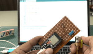
Now we upload the code and check the reading in a serial monitor
Serial Monitor OUTPUT
I hope you understand how the DHT11 sensor interfaces with the ESP32 board if you have any problems then comment it we try to Solve your problem.
Conclusion
In the project, we learned all about how you used the dht11 sensor. if you try to interface the sensor in another microcontroller then also you use the same code but the pin will change in the code.
ESP32 Projects





One Comment