Introduction
In this project, we learn how to make a Home Automation System using Blynk & ESP8266. One of the most common & Popular Hobby Projects you will come across on the internet is a smart home automation system. Home automation means controlling lights, climate, entertainment systems and appliances without a manual switch.
if you don’t know how the esp8266 board is used in Arduino ide then first check the Article
This home automation system controls home appliances such as TVs, FAN, BLUB, MOTOR, and REFRIGERATOR connected to relay using the Blynk Application.
This Board requires internet connectivity & if the internet is available then it controls the manual switch trough.
Bill Of Materials
The following are the components required for making this project. all the components can be easily purchased from Amazon or your local Market.
S.N | Component's | Quantity |
1 | NodeMCU (ESP8266) | 1 |
2 | 5V 1 channel Relay Module | 1 |
3 | Green Led | 1 |
4 | Yellow Led | 1 |
5 | Braed Board | 1 |
6 | 5 Pin Socket | 1 |
7 | Conecting Wire | 4 to 6 |
components
ESP8266 is a low-cost and WiFi-based microcontroller and is easy to use. It is based on ESP8266 and integrates GPIO, PWM, IIC, 1-Wire and ADC all in one board.
Features:
- 11 b/g/n Wi-Fi Direct (P2P), soft-AP
- Integrated TCP/IP protocol stack
- CP2102 Chip used for Serial communication
- +19.5dBm output power in 802.11b mode
- 4MB Flash Memory
- Integrated low-power 32-bit CPU
- SDIO 1.1 / 2.0, SPI, UART
- Output Voltage 3.3v
- Input Voltage 5v
5V Relay Module
A 5V 4-channel relay module that works with a low-level trigger voltage of 5V DC. The input voltage can be from any microcontroller that outputs a digital signal.
LED we used to check the Status of the Switch is ON Or Not When you click the on button the LED will be ON And when you click the OFF Button The LED will be OFF.
Circuit Diagram
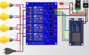
In this circuit diagram, we attach the 4-channel relay module in D1, D2, D5, D6 Pin Number in ESP8266 microcontroller Board. the power up the ESP32 Board With an External 5V Power Supply Through.
On the output Side Of the relay, the Module is connected to the AC Appliance and is connected to the AC(230v) Supply.
Blynk App Setup
ok,now let’s create the Blynk App Setup for this project.
First login the page or sign up.
Create the web dashboard and choose the name of the dashboard now I create the Name IoT App and take 4 simple switches and choose the virtual pin according to the code or Image.
Now edit the all switch names one by one and save them. you put any name according to the Your choice.
Now all the things are done just copy the Blynk Auth Token Key past in the code and upload to the ESP8266 Microcontroller Board.
Hardware
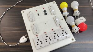
Here We show all the hardware which one i used to make the projects.
In the Box, we fix the NodeMCU(ESP8266) And 4 Channel Relay Module To Control the AC appliances Device In IoT Through.
Code
|
1 2 3 4 5 6 7 8 9 10 11 12 13 14 15 16 17 18 19 20 21 22 23 24 25 26 27 28 29 30 31 32 33 34 35 36 37 38 39 40 41 42 43 44 45 46 47 48 49 50 51 52 53 54 55 56 57 58 59 60 61 62 63 64 65 66 67 68 69 70 71 72 |
//Prateek //www.justdoelectronics.com #define BLYNK_PRINT Serial #include <ESP8266WiFi.h> #include <BlynkSimpleEsp8266.h> //Define the relay pins #define relay1 D1 #define relay2 D2 #define relay3 D5 #define relay4 D6 #define BLYNK_AUTH_TOKEN "duffshbjhvgvcccswqswsss" //Enter your blynk auth token char auth[] = BLYNK_AUTH_TOKEN; char ssid[] = "justdoelectronics";//Enter your WIFI name char pass[] = "Prateek";//Enter your WIFI password BLYNK_WRITE(V0) { bool value1 = param.asInt(); if (value1 == 1) { digitalWrite(relay1, LOW); } else { digitalWrite(relay1, HIGH); } } BLYNK_WRITE(V1) { bool value2 = param.asInt(); if (value2 == 1) { digitalWrite(relay2, LOW); } else { digitalWrite(relay2, HIGH); } } BLYNK_WRITE(V2) { bool value3 = param.asInt(); if (value3 == 1) { digitalWrite(relay3, LOW); } else { digitalWrite(relay3, HIGH); } } BLYNK_WRITE(V3) { bool value4 = param.asInt(); if (value4 == 1) { digitalWrite(relay4, LOW); } else { digitalWrite(relay4, HIGH); } } void setup() { pinMode(relay1, OUTPUT); pinMode(relay2, OUTPUT); pinMode(relay3, OUTPUT); pinMode(relay4, OUTPUT); digitalWrite(relay1, HIGH); digitalWrite(relay2, HIGH); digitalWrite(relay3, HIGH); digitalWrite(relay4, HIGH); Blynk.begin(auth, ssid, pass, "blynk.cloud", 80); } void loop() { Blynk.run(); } |
Demo of Projects
Now ESP8266 is Conected to the WiFi and is ready to work
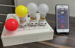
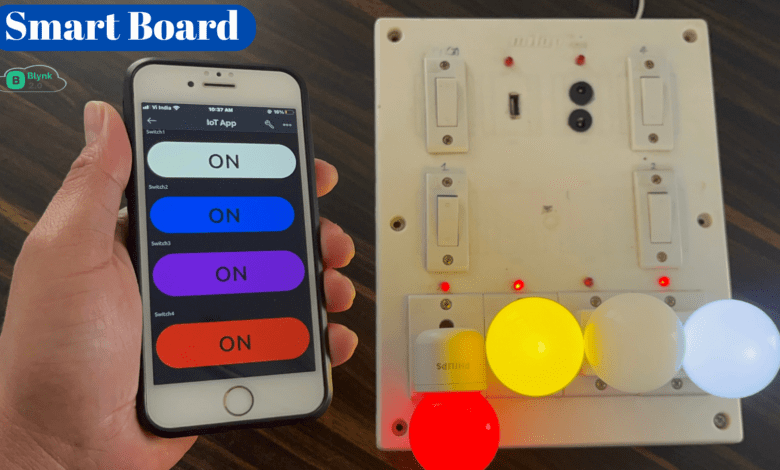
The Blynk App is conected and when you click the ON/OFF Mobile App Switch the AC Blub Will On&Off.
This Time we turn ON All the AC Blubs you see in the app Switch will ON.
