30+ DIY Projects Using Arduino Nano Development Boards
arduino nano tutorial for beginners
Introduction
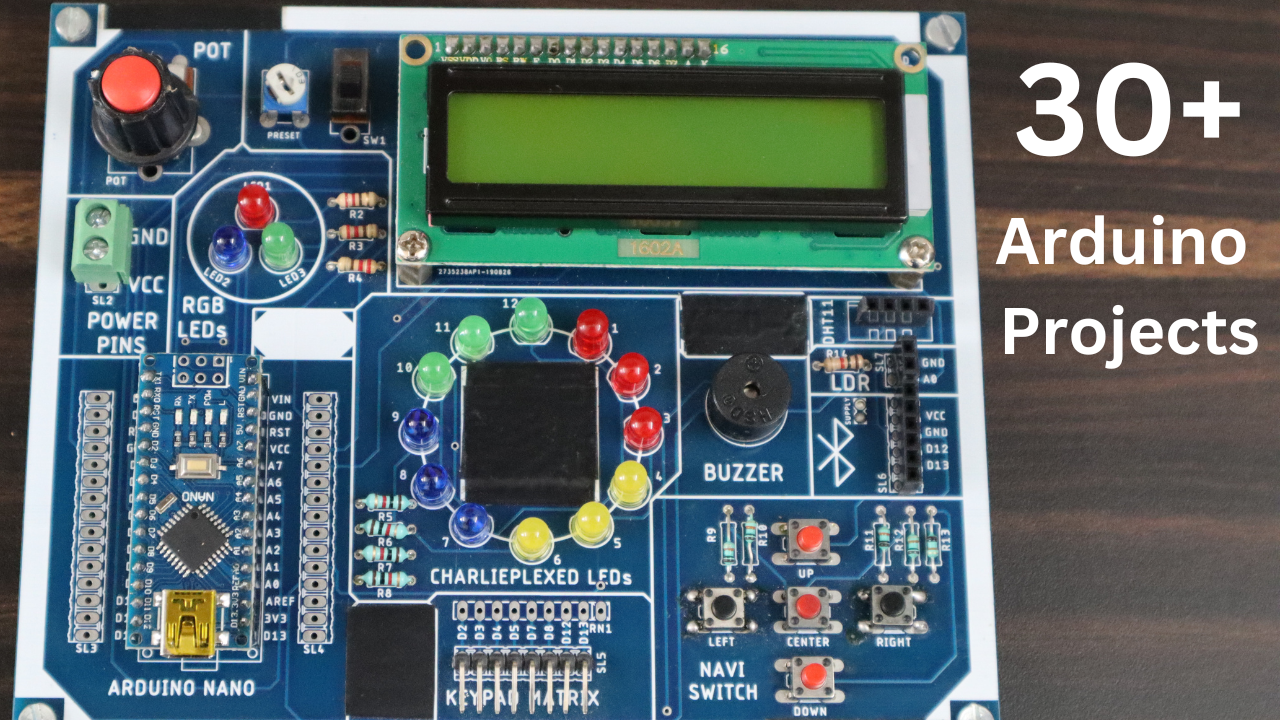
In this article, I will guide how you make 30+ DIY projects using these Arduino Nano Development Boards.
This Is A good Board for Biggner to Start The Arduino projects. Because in this Board Is Very Easy To connect the All Sensor & LCD.
Here is the Component List
S.N | Components | Quantity | BUY To LInk |
1 | Arduino Nano | 1 | |
2 | 16x2 LCD Display | 1 | |
3 | LDR Sensor | 1 | |
4 | Blutooth Module | 1 | |
5 | DHT11 Sensor | 1 | |
6 | Buzzer | 1 | |
7 | Push Button | 5 | |
8 | 10k Potentiometer | 2 | |
9 | Red Led | 1 | |
10 | Green Led | 2 | |
11 | Blue Led | 3 | |
12 | Sliding Switch | 1 | |
13 | Mix Led | 12 | |
14 | Male Header | 2 | |
15 | Female Header | 4 | |
16 | Resistor(220ohm) | 3 | |
17 | Resistor(10k) | 5 | |
18 | Resistor(4.7kohm) | 5 |

Just Check the Size Of the Arduino Nano Development Board


How To Use Board
If You are a Beginner and want to do it Practically then you can use this board very easily. I will give all the details step by step you just flow the blog and you easy to woo all 30+ Practical Very Easily. After doing all practicals you make a lot of real-life Application Projects.
In This Board, we used the Arduino Nano Board to control all things and we used too many components like a 16×2 Lcd Display, DHT11 Sensor, LDR Sensor, LM35 Sensor, Bluetooth Module, Led, Resister And Push Button.
ARDUINO IDE:- https://justdoelectronics.com/getting-started-with-arduino/
Arduino Nano
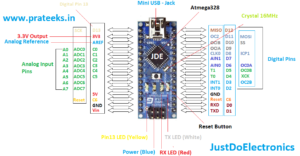
S.N. | Feature | Value |
1 | Microcontroller IC | ATmega328p |
2 | Digital Input/Output Pin | 14 (D0-D13) |
3 | Analog Pin | 8 (A0-A7) |
4 | PWM Pin | 6 |
5 | Built In Progammer | Yes |
6 | USB port | Yes Avilable (Type-B Micro Usb) |
7 | flash Memory | 32KB |
8 | SRAM Memory | 2KB |
9 | EEPROM | 1KB |
10 | Crystal Oscillator | 16 MHz |
11 | Operating voltage | 5V |
Experiment .1. ( LED Interfacing )
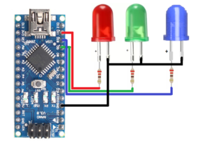
In this Board I used three led Red, Blue & Green. They Connected to the Arduino Nano pin D9, D10 & D11.
|
1 2 3 4 5 6 7 8 9 10 11 12 13 14 15 16 17 18 19 20 21 22 23 24 25 |
//Prateek //www.prateeks.in //www.justdoelectronics.com int green=9; int blue=10; int red =11; void setup() { pinMode(red, OUTPUT); pinMode(green,OUTPUT); pinMode(blue,OUTPUT); } void loop() { digitalWrite(red, HIGH); digitalWrite(green, HIGH); digitalWrite(blue, HIGH); delay(1000); digitalWrite(red, LOW); digitalWrite(green, LOW); digitalWrite(blue, LOW); delay(1000); } |
Experiment .2. ( LCD Interfacing )
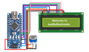
In this experiment, I just Connected the 16×2 Lcd Display using 4 bits. The LCD is 16 columns and 2 rows I mean one time you display 16 characters or Numbers.
16×2 Lcd Display

Features:-
- 16 Characters x 2 Lines
- Green Backlight
- 5×7 Dot Matrix Character + Cursor
- HD44780 Equivalent LCD Driver Built-In
- 4-bit or 8-bit MPU Interface With Any MicroController
The LCD pin Will be Connected to Arduino Nano
LCD Pin | Arduino Nano Pin |
GND | GND |
VDD | VCC |
VE (Contrast V) | POT 3 PIN (10K) |
RS (Register Select) | D4 |
RW (Read/Write) | GND |
E (Enable) | D5 |
D0 (Data Pin 0) | - |
D1 (Data Pin 1) | - |
D2 (Data Pin 2) | - |
D3 (Data Pin 3) | - |
D4 (Data Pin 4) | D0 |
D5 (Data Pin 5) | D1 |
D6 (Data Pin 6) | D2 |
D7 (Data Pin 7) | D3 |
LED + (+5V) | +5V |
LED - (GND) | GND |
|
1 2 3 4 5 6 7 8 9 10 11 12 13 14 15 16 17 18 |
//Prateek //www.prateeks.in //www.justdoelectronics.com #include "Wire.h" #include "Adafruit_LiquidCrystal.h" Adafruit_LiquidCrystal lcd(4,5,0,1,2,3); void setup() { lcd.begin(16, 2); lcd.print(" Welcome To"); } void loop() { lcd.setCursor(0, 1); lcd.print("JustDoElectronic"); } |
Experiment .3. ( Potentiometer With LCD Display)
In This Experiment, I just Display The Analog Value in a 16×2 Lcd Display. Here I just interfaced the 10k potentiometer to PIN A6 When I rotate the potentiometer clockwise or anti-clockwise the value will change.
|
1 2 3 4 5 6 7 8 9 10 11 12 13 14 15 16 17 18 19 20 21 22 23 24 25 26 |
//Prateek //www.prateeks.in //www.justdoelectronics.com #include <LiquidCrystal.h> LiquidCrystal lcd(4,5,0,1,2,3); void setup() { lcd.begin(16, 2); } void loop() { lcd.clear(); lcd.setCursor(0, 0); lcd.print("JustDoElectronic"); lcd.setCursor(0, 1); lcd.print("Value : "); lcd.setCursor(10, 1); lcd.print(analogRead(A6)); Serial.println(analogRead(A6)); delay(500); } |
Experiment .4. (Bluetooth-Based Notice Board )
In this experiment, I will connect the LCD module and Bluetooth module with Arduino Nano .fist I will connect to the Bluetooth module in our Mobile Apps, and when I send any Text That Text will Display In a 16×2 LCD.
Bluetooth Module
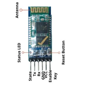
Specifications:-
- Bluetooth Protocol – V2.0 + EDR
- Frequency – 2.4 GHz
- Modulation – GFSK (Gaussian Frequency Shift Keying)
- Power Supply – 3.3v to 5v (50mA)
Applications:-
- Embedded Projects
- Industrial Applications
The Range the only 10 meters In the future I use the wifi module the Range is more than The Bluetooth module.
|
1 2 3 4 5 6 7 8 9 10 11 12 13 14 15 16 17 18 19 20 21 22 23 24 25 26 27 28 29 30 31 32 33 34 35 36 37 38 39 40 41 42 43 44 45 46 47 48 49 50 51 |
//Prateek //www.prateeks.in //www.justdoelectronics.com #include <SoftwareSerial.h> #include <LiquidCrystal.h> LiquidCrystal lcd(4,5,0,1,2,3); SoftwareSerial mySerial (12, 13); //(RX, TX); String val = "No Data"; String oldval; String newval = "No Data"; int i = 0; void setup() { mySerial.begin(9600); lcd.begin(16,2); lcd.setCursor(0, 0); lcd.print("Wireless Notice"); lcd.setCursor(0, 1); lcd.print(" Board "); delay(3000); lcd.clear(); lcd.print("Welcome!"); } void loop() { val = mySerial.readString(); val.trim(); Serial.println(val); if(val != oldval) { newval = val; } lcd.clear(); lcd.setCursor(i, 0); lcd.print(newval); Serial.println(newval); i++; if(i >= 15) { i = 0; } val = oldval; } |

