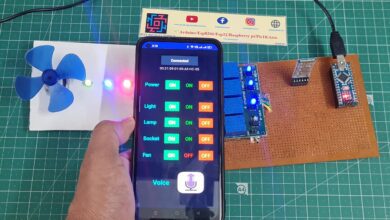
Gas And Temperature Monitoring With Arduino
Gas And Temperature Monitoring With Arduino
Introduction
In today’s fast-paced world, the need for remote monitoring and control systems has become increasingly important. Monitoring temperature and gas levels in various environments, such as industrial facilities, warehouses, and homes, is crucial for ensuring safety and efficiency. Traditional monitoring methods often fall short when it comes to providing real-time information and immediate alerts. However, with the combination of GSM technology and Arduino, a powerful and efficient monitoring system can be created.
We will begin by discussing the key components required to build this monitoring system, including the Arduino board, GSM module, temperature sensor, gas sensor, and LCD display. We will then guide you through the hardware setup and the necessary connections between the components. After that, we will delve into the software implementation, covering the code structure, sensor integration, data processing, and SMS alert functionality.
- Connect the Temperature sensor (LM35 Sensor) to the Arduino board using appropriate connections.
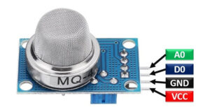
- Connect the gas sensor (MQ-135) to the Arduino board, ensuring proper connections for power, ground, and analog output.
- Connect the LCD display to the Arduino board using the I2C interface (if using an I2C-enabled LCD).
- Connect the GSM module to the Arduino board, establishing the necessary connections for power, ground, and serial communication.
Component Need
- Arduino Nano
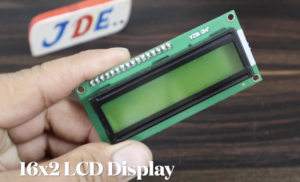
- 16×2 LCD Display (I2C)
- GSM SIM800l Module
- MQ-135 Sensor
- LM35 Sensor
- Relay Module
- LM2596 Step Down Conveter
- Buzzer
- Zero PCB
Arduino Nano
Here we used the Arduino nano micro controller to control all the input and out sensors or LCDs.in arduino they used the ATmega328 smd IC.
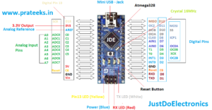
- The Arduino Nano has used an ATmega328P microcontroller chip.
- The ATmega328P operates at a clock speed of 16 MHz.
- Flash memory 32KB.
- SRAM of 2KB.
- 1KB of EEPROM.
- The Arduino Nano provides a total of 14 digital I/O pins.
- 6 PIN used for PWM (Pulse Width Modulation) output.
- 8 PIN analog input pins.
- 10-bit resolution.
Temperature Sensor
-
- Connect the LM35 temperature sensor to the Arduino board.
- Use the appropriate Arduino pins to read the analog output from the LM35 sensor.
- Convert the analog reading to temperature using the LM35 conversion formula.
- Store the temperature value in a variable for further processing and display.
Gas Sensor
-
-
- Connect the MQ135 gas sensor to the Arduino board.
- Use the appropriate Arduino pins to read the analog output from the MQ135 sensor.
- Implement a suitable calibration process for the MQ135 sensor to map the analog readings to gas levels.
- Convert the analog reading to gas level values based on the calibration data.
- Store the gas level value in a variable for further processing and display.
-
Sim800l GSM Module
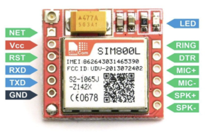
- The GSM module is a compact device that enables communication over the GSM network. It uses a Subscriber Identity Module (SIM) card to establish a connection with the cellular network.
- The SIM800L GSM module requires a stable and regulated power supply of around 3.7-4.2V.
16×2 LCD Display
- LCD Display: The LCD module consists of a liquid crystal display panel with 16 columns and 2 rows, allowing it to display up to 32 characters at a time. Each character is typically formed using a 5×8 dot matrix.
- I2C Interface: Interface SDA (Serial Data) and SCL (Serial Clock)
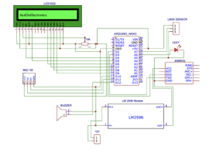
Circuit Diagram
Arduino Nano Connections
- The 5V pin of the Arduino Nano to the VCC pin of the GSM module, I2C 16×2 LCD display, and relay module.
- The GND pin of the Arduino Nano to the GND pin of the GSM module, I2C 16×2 LCD display, relay module, gas sensor, and temperature sensor.
GSM Module Connections
- The TX pin of the GSM module to the RX pin (Pin 10) of the Arduino Nano.
- The RX pin of the GSM module to the TX pin (Pin 11) of the Arduino Nano.
- The GND pin of the GSM module to the GND pin of the Arduino Nano.
I2C 16×2 LCD Display Connections
- The SDA pin of the I2C 16×2 LCD display to the SDA pin (A4) of the Arduino Nano.
- The SCL pin of the I2C 16×2 LCD display to the SCL pin (A5) of the Arduino Nano.
- The VCC pin of the I2C 16×2 LCD display to the 5V pin of the Arduino Nano.
- The GND pin of the I2C 16×2 LCD display to the GND pin of the Arduino Nano.
Relay Module Connections
- The control pin (IN1) of the relay module to a digital output pin (Pin 7) of the Arduino Nano.
- The VCC pin of the relay module to the 5V pin of the Arduino Nano.
- The GND pin of the relay module to the GND pin of the Arduino Nano.
Gas Sensor Connections
- The output pin of the gas sensor to an analog input pin (A0) of the Arduino Nano.
- The VCC pin of the gas sensor to the 5V pin of the Arduino Nano.
- The GND pin of the gas sensor to the GND pin of the Arduino Nano.
Temperature Sensor Connections
- The output pin of the temperature sensor to an analog input pin (A1) of the Arduino Nano.
- The VCC pin of the temperature sensor to the 5V pin of the Arduino Nano.
- The GND pin of the temperature sensor to the GND pin of the Arduino Nano.
PCB Design
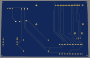
- Here we used the EasyEDA Software to design the project’s PCB
EasyEDA is a web-based electronic design automation (EDA) software that allows users to design, simulate, and prototype electronic circuits and printed circuit boards (PCBs). It provides a user-friendly interface and a set of powerful tools to assist in the entire process of electronic design.
MQ Sensor-Related Projects
Source Code
- Install the required libraries for the temperature sensor, gas sensor, and GSM module in the Arduino IDE.
- Write code to initialize the sensors, LCD display, and GSM module.
- Implement functions to read temperature and gas values from the respective sensors.
- Develop a routine to periodically read sensor data and update the LCD display.
- Integrate GSM functionality to send SMS alerts when abnormal temperature or gas levels are detected.
- Customize the SMS alerts with appropriate messages indicating the specific issue and location.
Project Demo
GAS Level Measurement
-
- The GAS sensor finds out the gas level in the room and displays it in the 16×2 LCD display.
- The Arduino Nano calculates the GAS Level Using the MQ-135 Sensor.
- Real-time water GAS readings are displayed on the LCD display.
Temperature Measurement
-
- The LM35 temperature sensor measures the water temperature.
- The Arduino Nano reads the sensor values and displays the temperature reading on the LCD display.
- Thresholds can be set to trigger alerts if the water temperature reaches critical levels, indicating potential issues or unsuitable conditions.
LCD Display With I2C
- Connect the 16×2 LCD display module to the Arduino board.
- Utilize the LiquidCrystal library and appropriate Arduino pins to control the LCD display.
- Write Arduino code to initialize the LCD display and display the gas level and temperature readings.
- Use the LCD display functions to show the measured values in the desired format.
GSM Alert System
- In the event of critical water level or temperature conditions, the Arduino Nano communicates with the GSM module to send SMS alerts to designated phone numbers.
- The SMS includes relevant information, such as the type of alert (GAS level or temperature) and the current readings.
Prototyping & Testing
-
- Assemble the components and connect them as per the circuit design.
- Upload the Arduino code to the board.
- Test the system by monitoring the temperature and gas levels and verifying the accuracy of the measurements.
- Test the GSM functionality by sending SMS or making calls to the designated recipient with the measured data.
Video Tutorial
Conclusion
By combining an mq-135 sensor, LM35 temperature sensor, GSM module, I2C 16×2 LCD display, relay module, and Arduino Nano, we have developed a smart gas monitoring system. This system offers real-time monitoring of gas and temperature, enabling proactive management and timely interventions. It can be applied in various air-related applications, promoting efficient resource utilization and preventing potential issues.
Arduino Based Projects

